Insights
J.S. Held Acquires Shechter & Everett to Expand Forensic Accounting Capabilities for Family Law Disputes in Florida
Read MoreFailure analysis is the scientific process of determining the root cause of a failure. It is often related to equipment breakdown with varying levels of consequence, from loss of production, to resulting damage to a significant amount of neighboring equipment. Failure analysis demands investigators maintain a high-level perspective, as well as a methodical approach to obtaining and sorting through details. To ensure that the pieces of the metaphorical puzzle fit to support the determination, investigators employ many tools, including expertise in various disciplines (requiring collaboration), site inspection and documentation skills, and analytical and laboratory testing.
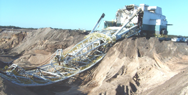
Figure 1 - Photograph of a failed dragline taken during a site inspection.
While site inspection and documentation are the wrench and screwdriver in the failure analysis toolbox used on nearly every job, sophisticated analytical and laboratory testing often provide the evidence to isolate the root cause of the failure. For instance, laboratory testing can determine the presence of material defects or progressive failure mechanisms, and analytical techniques can identify potential design defects or abnormal operating conditions.
Engineers use scientific/mathematical relationships to analyze how structures and equipment respond to operating conditions, such as a tank subjected to internal pressure. These calculations use simplified geometries and loading conditions to allow them to be solved by hand. The results provide an approximation that is often sufficient for developing a well-engineered design (when applying good engineering judgement).
However, with increasingly complex geometries and loading conditions, simple approximations may not be sufficient to provide accurate results. In these cases, analytical tools like finite element analysis (FEA) can be extremely beneficial. There are many misunderstandings and misconceptions about FEA, which this article aims to ameliorate. When used as one of the tools in a failure analysis, FEA can assist in finding errors in assumptions made during the design process, determine the effect of abnormal operating conditions, and determine how changes in component geometry, such as those that result from cracking and corrosion, have contributed to the failure.
In essence, FEA is a technique that allows components of complex shape to be broken down into many smaller, simpler shapes (elements) that can be analyzed more easily than the overall complex shape. This process of breaking the complex shape into elements is known as meshing. Analysis of the individual elements can be completed manually, but high-powered computing allows the necessary calculations to be solved rapidly.
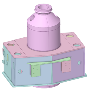
Figure 2 - Computer model of a hydraulic press head and cylinder.
FEA is a tool that can be used to solve various complex analytical problems including structural, vibration, fracture mechanics, thermal, buckling, and transient analysis. Future articles will include discussion of aspects of these different uses for FEA in greater detail and provide examples of how FEA has assisted in complex failure analyses.
FEA begins with creating a computer model of the component/structure that will be analyzed. When used for failure analysis, computer models of components or structures may already exist, which accelerates progress in completing the analysis. Often, however, the computer model has to be created based on drawings, 3D scans, and/or direct field measurements. Good engineering judgment is necessary to determine which aspects of the design must be included to provide the most accurate result. For instance, small features in structural components far from the failure location can often be omitted from the computer model.
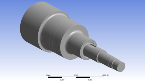
Figure 3 - Model of a turbine shaft.
After the computer model is completed, it is then meshed (i.e., broken up into elements). This process is extremely important to develop an accurate result and requires a separate article to adequately describe the process. That said, the model must be divided into a sufficient number of well-formed elements to accurately represent the shape of the overall component structure. Imagine cutting an intricate statue into simply shaped pieces—the more detailed the part of the statue, the smaller the pieces must be.
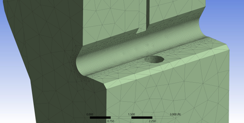
Figure 4 - Model of a structural column after meshing.
After meshing, the loading conditions are applied to the model, and the FEA software calculates the results based on the type of analysis selected. For instance, a thermal FEA will provide temperatures for given heating and cooling inputs, while a structural FEA will provide the extent of deformation or stress due to operational loads.
FEA has the potential to provide significant insight into the root cause of complex failures. Below are several analyses that demonstrate how FEA can be used as a practical and powerful tool in failure analysis.
The image below shows the results of an analysis of a pressure vessel that exhibited permanent deformation after being subjected to hydrotesting. For this matter it was important to understand what level of pressure resulted in the observed vessel deformation.
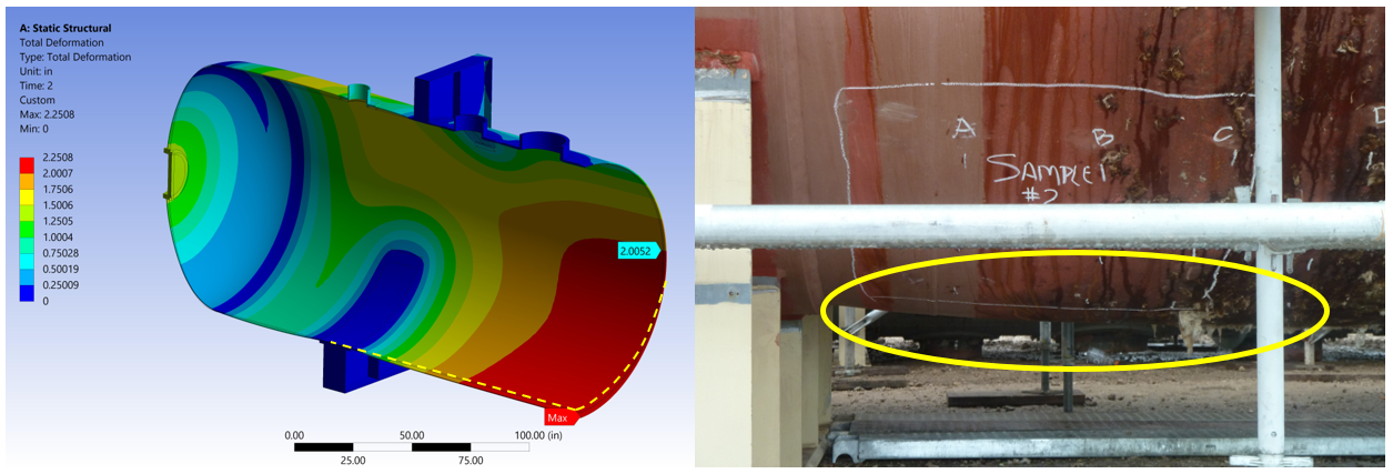
Figure 5 - Results of an FEA used to determine the extent of plastic deformation to a pressure vessel after overpressure (left), and inspection photograph of the actual vessel showing the deformation observed (right).
For this analysis, the material properties were determined from testing samples of the material of construction of the vessel. These properties were input into the FEA model and the magnitude of internal pressure required to generate the amount of permanent deformation actually observed was determined. This provides a great example of how when used together, site inspection and analytical techniques can provide results that would not be possible if used separately.
Structural components in a paper mill dryer began to exhibit cracking after over a decade of operation. Laboratory analysis determined that the cracking was due to high-cycle fatigue, a progressive cracking mechanism whereby repeated loading that results in alternating stresses of a significant magnitude, causes the initiation and propagation of cracks. The image below shows the results of an FEA of a component at the location where high-cycle fatigue cracking occurred.
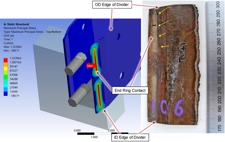
Figure 6 - Results of an FEA of a dryer component indicating high contact stress at the location of cracking.
The analysis determined that the design of the dryer did not properly account for expected operational loads, resulting in repeated stress cycles of a magnitude sufficient to result in high-cycle fatigue that progressed over a decade of operation.
Finite element analysis is an amazing addition to the failure analysis toolbox. When used in conjunction with sound site inspection and documentation skills, and laboratory analysis, the ability to determine the root cause of complex failures has few limitations. Experts trained in FEA regularly perform analyses that provide important insight into failures across a range of heavy industries, including energy, chemical, oil and gas, construction and manufacturing industries.
We would like to thank our colleague Andrew Marchesseault, PhD for providing insight and expertise that greatly assisted this research.
Dr. Andrew Marchesseault is a Vice President in J.S. Held’s Failure Analysis & Prevention practice. Dr. Marchesseault’s areas of expertise include failure analysis, fracture mechanics, thermal/fluid and mechanical analysis, Finite Element Analysis, and Computational Fluid Dynamics. Dr. Marchesseault has significant international experience, specifically with European companies, and is fluent in German. He has been involved in more than one hundred failure analyses of equipment in, among others, the marine, maritime, manufacturing, mining, energy, chemical, and oil and gas industries. He has conducted fracture mechanics analyses for components constructed of ferrous and non-ferrous metals, ceramics, composites, and polymers. He has also conducted Finite Element Analyses of complex geometries and loading conditions and is involved in on-site and laboratory inspections and root-cause analyses of insurance losses.
Dr. Marchesseault can be reached at [email protected] or +1 401 910 0121.
Insurance professionals, legal counsel, manufacturers, and others involved in claims or disputes stemming from material failures call upon materials science experts to determine the cause and origin of material failure(s). Fourier-Transform Infrared Spectroscopy (FTIR) is...
Infrared Thermography is the process of acquiring and analyzing thermal image information captured by a non-destructive thermal imaging device, often referred to as an infrared camera or an IR camera. These devices detect the heat...
Fuel station technology is evolving rapidly. Fuel dispensers, underground storage tank monitoring systems, and point of sale systems are closely integrated and reliant on each other for the station to function. If one component of...