Geotechnical engineers, civil engineers, structural engineers, construction managers, developers, and building owners involved in underground construction projects, as well as insurance carriers, builders’ risk insurers, insurance adjusters, construction defect attorneys, forensic consultants, expert witnesses, and contractors evaluating claims, failures, or litigation involving water intrusion and foundation performance, should read this article to learn more about:
Why a fully watertight, “bathtubbed” basement below the groundwater table is generally viewed as unrealistic.
How conventional drained foundations differ from waterproofed (tanked) systems, and the challenges faced by new developments in implementing on-site groundwater management and blindside waterproofing following City of Toronto’s 2022 Foundation Drainage Policy.
Risks shotcrete can introduce for blindside waterproofing.
Issues commonly observed in waterproofed systems.
Issues commonly observed in drained systems.
Design, detailing, and construction principles for both system types.
Mrinmoy draws on more than 18 years of geotechnical engineering and forensic investigation experience to explain why underground waterproofing failures often stem from overlooked design and construction details. He examines the practical challenges of drained versus waterproofed foundation systems, highlighting groundwater management strategies, common failure mechanisms, and lessons learned from forensic investigations.
Farhood leverages more than 25 years of civil and structural engineering experience to bring a constructability and risk-management perspective to below-grade waterproofing. His insights focus on how execution, detailing, and foundation wall construction methods can influence long-term performance and contribute to complex construction claims.
Richard draws on more than 30 years of international geotechnical and forensic engineering experience to contextualize the groundwater, excavation, and flooding risks that shape underground construction performance. His perspective underscores the importance of integrating drainage, waterproofing, and subsurface risk management into long-term infrastructure resilience.
Executive Summary
Waterproofing underground spaces below the groundwater table is a demanding task, and a fully watertight “bathtubbed” basement is generally considered unrealistic. This article reviews issues observed in recent mid-rise and high-rise projects with multi-level underground parking and compares conventional drained foundations with waterproofed (tanked) systems mandated by regulatory policies. Recurring problems include legacy drainage boards behind membranes, poorly detailed transitions and perforations, shotcrete-related membrane damage, omitted geotextile filters, and insufficient pumping redundancy. Because below-grade remediation is costly and intrusive, the authors offer practical design, detailing, and construction principles to manage groundwater and limit water ingress.
Introduction
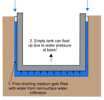
In the construction of building basements, tunnels, and shafts below the groundwater table, waterproofing and drainage components are critical items that require careful attention to details. Because fixing major deficiencies in these components is very difficult during later stages of construction and operation, getting the installation right the first time is vital to prevent severe consequences down the road. Let’s agree on this at the outset—adequately waterproofing underground spaces is not a simple task. This is especially true for structures extending deep below the groundwater table (e.g., more than 10 meters), as water under high hydrostatic pressure does not need much persuasion to force its way into an underground space. It is generally accepted among experienced practitioners that a perceived water-tight or so-called “bathtubbed” basement is unrealistic. It is fascinating how much pressure a thin continuous column of water can generate at the bottom of a structure: enough to cause accidental floating of heavy steel tanks or concrete reservoirs at water supply or treatment facilities when they are undergoing construction or emptied for maintenance (Figure 1a). Similarly, water pressure can force its way through cracks, construction joints, and transitions/overlaps in waterproofing membranes, often leading to flooded basements, or uplift basement slabs in extreme cases (Figure 1b). The pressure at the bottom of a 10-foot (3 m) tall, 1-inch (25 mm) diameter pipe is the same as the pressure at the bottom of a 10-foot-tall, 100-foot (30 m) wide tank; it is the height of the water column that matters.
Figure 1 - Water (a) lifts buried structures and/or (b) forces its way into subsurface structures.
Given the above, realistically speaking, since total water ingress elimination may not be practical or feasible, the key is to minimize water infiltration so that you are dealing only with “nuisance water” as part of regular maintenance, rather than major leakage problems. For waterproofed basements, it is also important to keep eventual leaks localized or “compartmentalized” by avoiding continuous high-permeability zones around the building’s basement, which can amplify the impact of local leaks and readily transmit water throughout the underground structure.
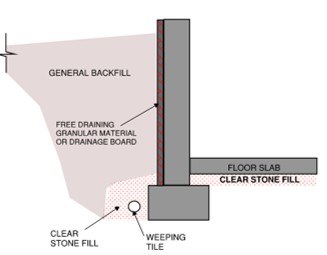
A recurring theme in forensic assessments of leaking basements is that the failure often stems from a lack of attention to small-scale details. This article looks at some common issues the author has observed in recent projects involving mid-rise and high-rise towers with multi-level underground parking and outlines general principles for groundwater control for both conventional drained (e.g., slab-on-grade foundation) and water-tight (e.g., raft foundation) systems (Figure 2).
The City of Toronto’s Foundation Drainage Policy, introduced in 2022, restricts the discharge of foundation drainage (groundwater/infiltrated stormwater) into municipal sewer systems, aiming to preserve sewer capacity and reduce flooding [1]. As a result, most new developments manage foundation drainage on-site rather than use traditional permanent drainage connections. New developments are encouraged to use waterproofing measures, such as “fully tanked”/“bathtubbed” raft foundations, or to ensure on-site infiltration, e.g., bioswales. Considering, too, the increasing use of “blindside” waterproofing [2], new challenges have arisen for underground infrastructure development, especially for private land development projects, as the industry adapts. The margin of error is small, and even minor oversights in execution can lead to systemic, multi-million-dollar failures with potential added ongoing maintenance, repair, and service issues.
Issues with Waterproofed Basement Systems
Legacy Design Details from Drained Systems
In waterproofed (“bathtubbed”) basements, a waterproofing membrane is placed continuously along the exterior surfaces of the basement walls, and the lowest slab level, i.e., the entire underground portion of the structure below the groundwater table, is enveloped within a waterproofing membrane (Figure 2b). These systems are designed to resist hydrostatic pressure, as exterior drainage measures are not provided. On the other hand, in conventional drained systems, vertical drainage boards (Figure 2a), placed against the outside face of foundation walls, and under-slab drainage pipes relieve hydrostatic pressure by directing water to a drainage system (e.g., perimeter weeping tiles) at the bottom.
The use of such exterior drainage boards against the foundation walls can be counter-productive in a "bathtub" system, as they facilitate storage of groundwater against the foundation wall, allowing water to flow freely and collect around the entire structure, thereby exacerbating local leaks. To mitigate this risk, the drainage board should be eliminated, and the waterproofing membrane should be applied directly to a smooth, relatively impermeable surface, such as the interior face of a diaphragm soil retention wall. This approach reduces the volume of water held directly against the foundation wall and lessens the risk of excessive water infiltration, should leakage pathways develop through the waterproofing envelope.
Handling of Complex Interfaces, Transitions, Perforations, and Surface Preparation
Below-grade structures often require the integration of multiple waterproofing materials, creating vulnerable "transition zones." For tunnels, leaks are often concentrated at the intersections between the tunnel and the access shafts. These areas are notoriously difficult to waterproof due to complex geometry and the need to bond two different systems. The same is true for building configurations with raft slabs at different levels and footprints with re-entrant corners.
In theory, the waterproofing membrane wraps around and envelopes the basement. However, the waterproofing system contains numerous overlaps between membrane sheets and joints where perforations, such as tieback intrusions and temporary groundwater control pipes, exist. Proactive measures, such as designing tieback boxes, help reduce or eliminate the risk of "difficult detailing" or site fabrication during membrane installation and ensure that such intrusions do not become permanent leak paths into the basement.
For hydrophilic membranes [3], it is important to provide a solid, unyielding substrate to ensure confinement and prevent uncontrolled membrane swelling. For soldier piles and lagging shoring systems, it is important to minimize over-excavation and fill any voids behind the lagging with well-compacted materials to ensure a tight fit of the lagging, which, in turn, will provide the confinement needed for effective performance of hydrophilic membranes.
Use of Shotcrete for Foundation Wall Construction
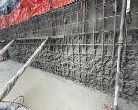
The choice of concrete placement method for foundation wall construction significantly impacts waterproofing integrity. Shotcrete [4] is popular for its ability to speed up schedules, but it introduces risk factors for blindside waterproofing, as follows:
Figure 3 - Use of shotcrete for foundation wall construction.
Overspray: Wet concrete splatter on the membrane of adjacent panels acts as a bond breaker, preventing the adhesion required for many systems to be effective.
Membrane rupture/separation: Shotcreting can rupture the membrane or separate the seams if a uniform backing is not provided. It is particularly possible around the tie-back ends.
Rebar shadowing: If shotcrete is not applied correctly, voids (shadows) can form behind the reinforcement steel, creating cavities where water can collect.
Poor consolidation: Without proper vibration and flow, concrete may become honeycombed at the contact point with the membrane, compromising the seal.
Issues with Drained Basement Systems
Installation Deficiencies for Drained Foundations
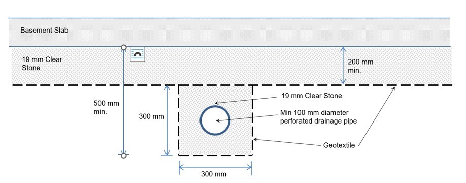
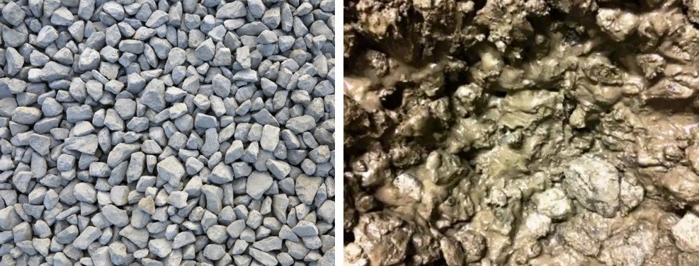
Conventional drained foundations often use clear stone materials under the basement slab, along with perforated drainpipes for groundwater drainage. It is important to fully wrap clear stone materials with geotextile (filter fabric) when they are used in underground construction. If this critical component is omitted during construction, fine soil particles such as fine sand and silt beneath the slab can wash into it over time due to groundwater flow. This will plug or “gum up” the void spaces in the clear stone, reducing their drainage function and leading to both 1) soil loss below the floor slab, leading to cracking and settlement, and 2) groundwater pressure buildup and eventual leakage inside the basement through joints and cracks in the floor and walls, since water cannot effectively be discharged from under the slab.
Figure 4 - Typical under-slab drainage details.
Figure 5 - Under-slab clear stone (a) without contamination (b) contaminated with fine soil particles.
Flooding Risks in Drained Foundations
Since drained systems are not waterproofed, they rely heavily on the efficacy of the drainage components to prevent water ingress and flooding. The drainage components of a drained foundation system are highly permeable compared to the ground adjacent to the structure, especially for basements constructed in bedrock or clay soils.
Typical components of the drainage system consist of the following:
A network of perforated pipes (“weeping tiles”) beneath the lowest basement level. Often, the weeping tiles are encapsulated in clear stone material within trenches.
A 200 mm or so thick clear stone base layer placed beneath the lowest level slab, which acts as a slab base and moisture barrier.
A network of solid collector pipes, which carry the water collected by the weeping tiles to sump pits or groundwater storage tanks.
A perimeter drainage system consisting of vertical drainage boards (e.g., Mira-Drain) located outside of the basement foundation walls, i.e., placed between the shoring wall and the permanent basement wall, and an exterior weeping tile with clear stone surround looping around the building.
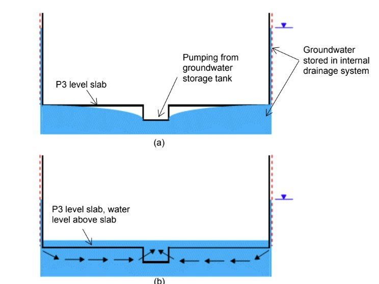
For typical multi-level underground structures, the combined volume of these free-draining materials can exceed 1 million liters. When subjected to high groundwater levels outside the basement (e.g., during spring thaw or heavy rain events), these components can be fully saturated, with a hydraulic head equal to the outside groundwater level. If sufficient discharge pumping capacity is not provided or if pumps fail without any backup capacity, the stored water can drain rapidly into the basement, inundating the space.
Figure 6 - Flooding risk in drained basements (a) groundwater under control when the pump is working (b) groundwater forcing its way in after pump failure.
Principles to Consider for a Drained System
1. Minimize surface water infiltration into foundation backfill
Minimizing infiltration through proper grading and imperviousness is critical because water in the backfill acts as a "recharge" source, creating or sustaining hydrostatic pressure. Surface water infiltration can significantly increase the load on the pumping system.
2. Provide adequate discharge capacity and backup pumps
Drained basement systems rely on adequate pumping/removal of water from interior sumps/stormwater tanks. When the system can no longer discharge the collected water efficiently, groundwater pressure builds up below the floor slab and behind the foundation walls, eventually causing seepage through joints and cracks in the parking garage and, in extreme cases, flooding.
3. Mind the construction details
It should be ensured that geotextile filter fabrics are installed with adequate overlaps to fully separate the native soil and the drainage stone placed under the floor slab. Without this filter, fine soil particles (fine sand, silt, and clay) will gradually fill the void spaces in the drainage stone, reducing its drainage efficiency.
Gaps around pipe entries in interior catch basins and between the pre-cast segments of sump pits often act as unintended pathways for sediment to enter the drainage system. These details should be carefully checked during construction to help ensure the structure's design service life.
4. Keep perimeter and under-slab drainage systems separate
It is often a good idea to design two independent drainage systems: a perimeter wall weeping tile system and an independent under-slab drainage system. The solid pipes carrying water from the exterior perimeter drains should not be connected to the under-slab drainage system. This separation is considered an appropriate engineering practice to ensure that water collected from outside the foundation walls (often under different pressure or volume) does not overwhelm the sub-slab network.
Principles for Waterproofed Foundation Systems
1. Omit drainage boards against the foundation walls
Do not provide unnecessary free-draining storage space, such as drainage boards/mats, behind the waterproofing membrane, where water can accumulate and move freely through this medium around the building.
2. Carefully evaluate the risks of using shotcrete
Carefully evaluate the risks of damage to the waterproofing membrane, overspray, and membrane debonding if shotcrete is considered for constructing the foundation walls. Using two layers of membrane with interlaced seam locations is recommended for shotcrete application.
3. Consider interior drainage for under-slab management
Often, waterproofed raft foundations use slab-on-grades separated from the raft by a 1 m-thick clear stone layer. This space is utilized for mechanical/utility pipes. It is prudent to provide internal drainage for this clear stone material (Figure 2b). Otherwise, even minor water leakage can direct groundwater to this space, which slowly accumulates and leads to water ingress problems down the road.
4. Mind the construction details
If the intent is to build a waterproofed system, transitions such as re-entrant corners and adjacent raft slabs at different levels should be omitted at the design level to the extent possible. Otherwise, extra attention should be paid to waterproofing detailing around these transitions, and adequate membrane overlaps should be provided. Perforations through the waterproofing membrane should be minimized, for example, by using A-frame formwork rather than relying on rebar pieces attached to the shoring to support the temporary concrete formwork. The backing medium for the membranes should be solid/unyielding, and compressible boards or uneven lagging boards should be avoided.
Conclusion
While localized/minor leaks and some repairs (e.g., spot injections) are expected for almost all systems, major remediation of a failed below-grade waterproofing system or drainage components is a physically daunting task and a significant financial expense. Exterior excavation for access and repair/replacement is not a practical remediation option in most cases. Instead, owners are often forced to resort to remedies such as curtain wall grout injection, a costly and intrusive process that involves drilling through the foundation to inject polymers or foams into the soil-structure interface.
In light of the challenges faced by the industry, it is possible that current regulatory policies that push new developments toward fully waterproofed construction may be revisited, and groundwater management options for new development applications may be evaluated on a case-by-case basis. Regardless of any future amendments to such policies, the goal is to install the waterproofing or drainage systems correctly the first time, with due attention to the details. Adherence to the above principles, engaging qualified designers, installers, quality control personnel, and effective coordination during construction can help avoid problems or, at the very least, minimize them.
Acknowledgments
J.S. Held would like to thank Mrinmoy Kanungo, Dr. Farhood Nowzartash, and Richard Stahl for providing insights and expertise that greatly assisted this research.
More About J.S. Held’s Contributor
Mrinmoy Kanungo is a Vice President in J.S. Held’s Forensic Architecture & Engineering practice. Mrinmoy has over 18 years of geotechnical engineering consulting experience in design consulting, construction services, and forensic investigations involving foundations, slopes, earth embankments, retaining walls, excavation support systems, tunnels, trenchless technology installations, pavements, and utility lines. Mrinmoy has led many multidisciplinary forensic investigations and has executed peer review work on complex insurance and legal claims, spanning a wide range of residential, commercial, and industrial sectors within North and South America. Mrinmoy is involved in forensic investigations of complex geotechnical and geo-structural engineering matters and subsurface (earthwork) construction risk advisory services. Mrinmoy’s responsibilities include business development, service line brand building, and growing the geotechnical team.
Dr. Farhood Nowzartash is a Senior Vice President and Canada Lead in J.S. Held’s Forensic Architecture & Engineering practice. He is a qualified expert witness in Civil/Structural Engineering with a specialty in the forensic investigation of complex construction claims/litigation matters, the standard of care assessment and root cause analysis. He has over 25 years of experience in structural design and construction, including reinforced and pre-stressed concrete, structural steel, formworks, and wood structures. He has been an active member in the design process of multi-story and high-rise buildings, low-rise commercial buildings, bridges, oil and gas pipelines, sports complexes, stadiums, earth shoring, and concrete shoring. In addition, he has extensive experience with forensic investigations, large-scale commercial losses, industrial losses, building systems, surface water management, structural failure analysis, seismic hazard assessment, building rehabilitation, and stress analysis of component failures using Finite Element Modeling.
Dr. Nowzartash can be reached at [email protected] or +1 416 458 2496.
Richard Stahl is a Senior Vice President in J.S. Held’s Forensic Architecture & Engineering practice. Richard has more than 30 years of international experience as a geotechnical engineer and forensic investigator. He has led multi-disciplinary teams for large scale project developments and forensic investigations and provided expert testimony at trial, arbitrations, and mediations. Richard has been engaged in multi-million-dollar assignments within a variety of business sectors, including mining, energy, natural resources, industrial, commercial, heavy civil infrastructure, marine, transportation and distribution, real estate, hospitality, and tourism/recreational sectors within the Americas and Asia. Notable assignments include flooding investigations and remediation in the Bahamas, shallow and deep excavations in North America, tunneling in Asia and North America, and slopes, water resource, and mine tailings dams in North and South America and Australasia.
[1] The City is scheduled to amend the policy to allow a limited quantity of foundation drainage containing groundwater to be discharged into the City's storm sewers, under certain conditions.
[2] Blindside waterproofing is a specialized below-grade technique used when sloped excavation and access outside the foundation wall is impossible, such as in dense urban areas with zero-lot. The waterproofing membrane is applied to the soil retention/shoring wall first, and then foundation wall concrete is poured directly against it.
[3] Hydrophilic membranes expand when they come into contact with water. This swelling action, when it occurs under a controlled manner, actively fills gaps, cracks, and fastener penetrations to prevent water migration through the membrane.
[4] Shotcrete is concrete pneumatically projected at high velocity onto a surface, which allows for precise application on complex shapes and vertical or overhead surfaces without extensive formwork.
[5] City of Toronto, Foundation Drainage Policy, November 1, 2021 (applicable to development applications as of January 1, 2022).
How geology, groundwater, and geometry impact construction and repair activities, associated risks, and methods used to navigate these complexities....
How careful consideration of soil properties helps avoid potential building hazards and risks arising from weaknesses or distractions beneath the surface....